With the surge in demand for electric vehicles, the race is on to develop cutting-edge, energy-efficient charging infrastructure that can power up our vehicles quicker than ever before. Gone are the days of fretting over battery capacity and range anxiety; the automotive industry is witnessing a monumental shift, all thanks to relentless innovation in the EV sector.
Enter fast DC charging—a game-changing solution poised to revolutionize the EV landscape. In this article, we’ll delve deeper into the realm of power electronics applications within EV charging stations, shining the spotlight on various electrifying topologies that are propelling us towards a greener tomorrow.
Before going deep into power electronic topologies, we will first know more about the charging infrastructure for electric vehicle. A charging station, also known as Electric Vehicle Supply Equipment (EVSE) or Charging point is a part of Grid infrastructure and used for supplying electrical power to plug-in electric vehicles for charging battery packs.
The charging stations can be installed in public places like on the street side, at government facilities and retail shopping centres/malls, or can be seen in isolated areas like residences, hotels, and workplaces.
Understanding the Different Types of EV Chargers
Electric vehicle batteries can only be charged by DC power supply, but the main electricity that gets delivered from the power grid is AC. Therefore, all electric vehicles require AC-to-DC converter for charging the battery.
Electric vehicle battery chargers fall into two categories: off-board and on-board, and they can have either unidirectional or bidirectional power flow capability.
- In an AC charging station, AC supply from power grid is supplied to electric vehicle batteries through the vehicle’s On-board charger which converts AC into DC power. These onboard chargers are present inside the electric vehicle and are designed for lower kilowatts of power transfer. AC charging stations are slow charging stations and are the most widely used charging method.
- In DC charging stations, the AC to DC converter is present outside the electric vehicle and are known as Off board chargers. These DC chargers provide higher power charging by placing the converter inside the charging station instead of the vehicle to avoid size and weight restrictions which can increase the vehicle’s overall efficiency. The station directly provides DC power to the vehicle, bypassing the converter installed onboard.
The onboard and off-board chargers for a Plug-in electric vehicle are illustrated below.
Choosing the Right EV Chargers
It is important to understand different types of EV chargers available in the market which are used in AC and DC charging stations. These EV chargers are classified based on power levels, battery charging time and their application. There are three main types of EV chargers: Level 1, Level 2, and DC Fast Chargers.
| Parameters | L1 Charger | L2 Charger | DC Charger |
| Charging station | AC | AC | DC |
| Voltage source (V) | 120/230 VAC, single phase | 208-240 VAC, polyphase | 300-600 VDC |
| Charging Current (A) | 12-16 | 15-80 | 400 |
| Charging time (Hrs) | 12-17 | 6-8 | 0.5-1 |
| Speed | Slow | Semi fast | Faster |
| Type | Onboard charger | Onboard charger | Off board charger |
| Location | Residential | Residential/ Commercial | Commercial |
Each EV charger has its own advantages and disadvantages. It is important to consider crucial factors like charging needs, vehicle compatibility and power output of electric vehicles before selecting right kind of charger. L1 and L2 chargers are suitable for short commute and daily usage whereas DC fast chargers are ideal for long trips and quick top up of batteries.
L1 chargers are slow but can be plugged into any standard outlet. Level 2 chargers are the popular choice for home charging and take less time than L1 chargers.
Check out our blog on EV charging for more information on home charging and public charging.
Role of Power Electronics in Battery Charging System
Power electronic converters play a vital role in battery charging systems. It controls the charging process and manage power flow when the vehicle is connected to a charging station. DC charging stations require high power modular converters which are capable of fast charging.
Few important characteristics of power converters in battery charging system are their energy density, efficiency, and capacity to regulate voltage and current as per battery requirement.
Power Converter Topologies for DC Fast Charging
Typically, an EV battery charger consists of two stages of conversion. One is AC-DC conversion stage for rectification of incoming AC power from Grid into DC power required and guarantees unity power factor.
Second one is DC-DC conversion in which DC voltage is stepped up or stepped down to match the specific requirements of batteries. This voltage varies as per the state of charge (SoC) of battery pack.
Let us first see the different types of power converter topologies used for DC Charging stations and then for AC charging stations.
AC-DC Power Converter
The first level of power conversion in EV charging station is AC-DC power conversion, which is also known as PFC (Power factor correction) stage. AC-DC power converter converts the incoming AC voltage of 380-415 V into stable DC link voltage of 1000 V.
With the presence of filter, a phase shift between the sinusoidal AC power supply voltage and current can happen and the power factor (PF) drops. A power factor correction (PFC) circuit reduces the harmonic distortion in the supply current and creates a current waveform close to a fundamental sine wave to increase the power factor to unity.
Thus, PFC stage helps in maintaining sinusoidal input current to give controlled DC output voltage. Power factor correction helps in increasing power efficiency under the same input conditions.
PFC topologies are of three types – passive, hybrid, and active PFC rectifiers. Depending on power level, it is of two types – single phase and three phase PFC converters.
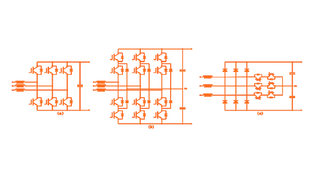
For fast charging application, high efficiency and smaller size, the most suitable PFC topologies in an EV charging station are three phase active PFC rectifiers which can be used for high power level above 3.3 kW. A boost chopper is a basic topology of any active PFC topology. Three phase active PFC rectifiers are of different types – two level PFC, Neutral point clamped (NPC) PFC and Vienna PFC.

- A three phase two level PFC rectifier supports bidirectional power flow operation and generates low total harmonic current distortion with a power factor close to unity. It consists of a bridge rectifier with six controlled switches. It provides good efficiency and easy control but are bulky in size due to filter inductors which are required for regulating THD level.
- Neutral point clamped PFC rectifier is another type of PFC rectifier which uses the Neutral Point Clamp scheme commonly found in inverter circuits. It consists of a bridge rectifier with twelve controlled switches and six diodes. It has higher efficiency (low power loss) due to adoption of multi-level scheme. This topology also has a bipolar DC bus which helps in increasing power levels by connecting two DC-DC converters in either series-series or series-parallel configuration. The major drawback of this converter is the number of semiconductor switches which make the circuit costly, bulky & complex.
- The Vienna PFC rectifier is more popular than the other rectifiers as it provides power factor close to unity and low total harmonic distortion. It has less complex circuit due to reduced number of controlled switches and has high power density as it requires only half of the inductance for the boost inductors. Its only drawback is that it only supports unidirectional mode power transfer from the grid to the DC side.
Among all the three PFC topologies discussed, Vienna PFC is most cost effective and gives quality output voltage and input current whereas NPC PFC is best suited for high power density and bidirectional power flow.
DC-DC Power Converter
The second level of power conversion in EV charging station is DC- DC conversion. The Buck converter is used, as the battery voltage is less than the output voltage of the rectifier. It converts the incoming 800 DC voltage into lower DC voltage depending on the State of Charge (SoC) of the battery while ensuring safe operation by communicating with the BMS. DC-DC converter can deliver wide range of voltage (50-500V) at rated power to a battery, for example 48 V to a two-wheeler electric bike and upto 500 V to plug-in electric vehicle.
There are two types of DC-DC converters based on the presence of galvanic isolation provided by the power transformer on the grid side: isolated DC-DC converter and non-isolated DC-DC converter. If the galvanic isolation is present on the power transformer, then non isolated DC-DC converter is used, otherwise isolated DC-DC converter can be used.
- Three-phase interleaved DC-DC converter – The three-phase interleaved DC-DC buck converter is a type of non-isolated DC-DC converter which can be used for decreasing the input voltage and high current application with lower size inductor filters.
- Three-phase interleaved DC-DC converter – If bidirectional flow is required between grid and electric vehicle power storage, a three-phase interleaved DC-DC buck-boost converter can be used in charging stations.
If no galvanic isolation is provided on the grid side, a transformer is provided along with DC-DC converter for galvanic isolation and operational safety. The most popular isolated DC-DC buck converters are Phase shift full bridge (PSFB) converter and Dual active bridge (DAB) converter.
- The phase shift full bridge DC-DC converter (figure a) consists of a transformer for isolation and has primary and secondary side. Its primary side consists of an H bridge with controlled switches and secondary side consists of H bridge with diodes which are connected to batteries. This converter can be used only for unidirectional power flow but can deliver high output voltage and power rating with good efficiency. Both Zero current switching (ZCS) and Zero voltage switching (ZVS) can be performed in this converter.
- For bidirectional power flow a Dual active bridge DC-DC converter (figure b) can be used in place of a PSFB DC-DC converter for EV charging stations. The major difference is that on secondary side, diode bridge is replaced by H Bridge controlled switches which helps in bidirectional power flow. The disadvantage of this topology is the complex circuit due to control of eight power switches and non-resonant operation which results in less efficiency at low power rating.
Power Converter Topologies for AC Fast Charging
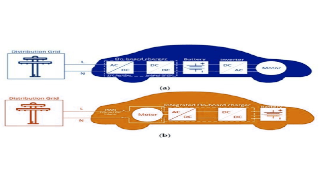
AC charging typically needs an on-board AC-DC power converter. Interestingly, both the motor and the motor drive inverter serve dual purpose. They not only convert DC power from the battery into AC power for the motor but also function as the on-board charger for the battery. This integration removes the necessity for a distinct AC-DC power converter dedicated to the on-board charger.

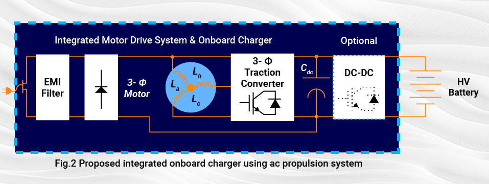
An integrated on-board EV charger is a bidirectional EV charger that operates in all EV operation modes using a single inverter/rectifier. The EV traction/propulsion, braking, and battery recharging all utilize the same power switches, which allows for a reduction in the number of power electronic devices.
In this way, the EV charger’s price, dimensions, and weight are significantly decreased. Recently, this technology has come to light as an ideal solution between off-board and on-board battery chargers.

During propulsion, the battery provides the propulsion power through a three-phase traction converter (inverter mode) and the additional diode bridge has no influence on the traction converter operation. While the battery is in charging mode, the grid AC line voltage is rectified by the diode-bridge and the propulsion machine windings while the traction converter develop a two-channel interleaved boost converter, which is utilized for PFC and output voltage/current regulation.
In order for this method to be effective, it must fulfill specific technical criteria throughout the charging procedure, including minimal or no alteration to winding configurations and maintaining an average torque of zero.
Conclusion
This article is a useful guide that provides a comprehensive overview of EV chargers and types of power converter topologies used inside the EV for fast charging. The selection criteria for EV chargers depend upon efficiency, durability, performance, and cost. With the increase in charging power demand for different levels and evolution of the vehicle electrical system, new types of DC and AC chargers are emerging. These types of chargers provide high power and have a compact architecture and low cost.


