Car manufacturers have been able to enhance driving experiences by adding various interfaces to vehicle dashboards. So, when your screen flashes low tire pressure, it is in a way adding years to the tire’s life, maintaining fuel efficiency, and ensuring better ride quality. Timely and accurate display of tell tales like tire-pressure, seatbelt sign, door open/close warnings go a long way in ensuring that the driver and occupants are safe and are able to enjoy an enhanced ride quality.
The keywords to be noted in the previous paragraph are ‘timely’ and ‘accurate’. And it is due to these two very important factors that functional safety comes into the game. Automotive displays like Digital Instrument Cluster provide safety-critical information to the driver through visual alerts like flashing lights. If you add ADAS related warnings to the mix, you get an instrument cluster that is safety-critical to its highest limit, i.e., ASIL D. It is essential that such a cluster is highly reliable and displays warnings about safety-critical functionality with utmost accuracy. And in order to achieve such reliability, adherence to ISO 26262 standard is the way to go.
ISO 26262 for digital instrument clusters does not work differently. You have the same lifecycle to follow, beginning with item definition, HARA, various safety analyses like FMEA, FTA and testing. So why are we writing a whole new article stressing about FuSa for digital instrument cluster?
For one, as a technology provider, we have been fortunate to work on some really challenging ISO 26262 compliant digital instrument cluster projects. Another reason is that instrument clusters and other automotive displays are not usually considered safety critical. ASIL is assigned to them based on assumptions or industry norms. And that can prove to be a disaster in more ways than one can imagine.
A Closer Look into Digital Instrument Cluster to Understand Its Safety-Criticality
The first ever application of an instrument cluster in a passenger vehicle was in an Aston Martin vehicle in the year 1979. It was a basic instrument cluster showing vehicle speed, kilometers driven and fuel meter, to name a few. Fast forward to the era of e-cockpit*, digital instrument cluster is a goldmine of vehicle information.
*E-cockpit is a concept where an interactive multi-dimensional control center displays a wealth of vehicle related information on the screen and lets the vehicle occupant control a host of vehicle features with a few clicks. Usually, an e-cockpit comprises infotainment system, digital instrument cluster and head-up display.
A digital instrument cluster completely replaces a traditional analog instrument cluster. To make it truly digital, a combination of system-on-chip (SOC), display unit and software work in tandem. OEMs design instrument clusters in a very personalized manner; however, there are certain functionalities that most advanced clusters will have:
- Vehicle information (speed, tell tales, battery, etc.)
- Turn-by turn navigation system
- Call alert
- Weather information
- Music playback display
- Mechanism to upgrade the software/firmware
- On-board ambient light sensor
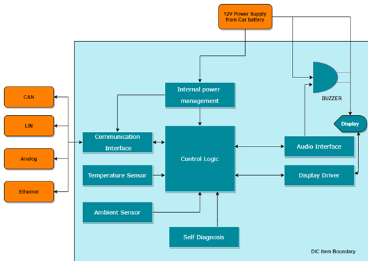
An instrument cluster system collects vehicle information from various ECUs and sensors through the vehicle network systems such as CAN, LIN, FlexRay and even Ethernet. There are interfaces such as communication interface and audio interface that make the data available to the instrument cluster display. The diagram below highlights all the elements that constitute a digital instrument cluster.
Whether a connected cluster is safety-critical is roughly decided by the kind of signals it is transmitting, processing and displaying. Obviously, a detailed HARA should be done to ascertain the ASIL value and safety goals.

The following elements of the digital instrument cluster are considered in the safety scope:
| 1 | Control logic | This executes all core algorithms and functionalities. It controls all major components and achieves the safety measures required in the system. |
| 2 | Internal power management | Provides regulated safe power supply to various elements. Certain safety features need to be implemented in this element. |
| 3 | Communication interface | Includes Protocol specific transceivers, connectors, harness, etc. |
| 4 | Self-Diagnosis | On board fault detection and handling mechanisms. |
| 5 | Temperature sensor | To monitor the processor board surrounding temperature. |
| 6 | Ambient light sensor | To adjust the display brightness automatically. |
| 7 | Display | An interface/driver to make sure the display is set properly and helps to show the content in the display. However, this is not responsible for all display faults occurring during the runtime. |
| 8 | Display Driver | If any fault is sent by display, it resets the fault by taking the appropriate action, such as restarting the display or switching it off. |
| 9 | Buzzer/Speaker | To play the Audio for important alerts, warnings, and errors. |
| 10 | Audio driver/interface | Helps to decode and play the audio and send to speaker. |
All these elements are responsible for making the digital instrument cluster perform its function. It also implies that these elements need to be developed in accordance with ISO 26262 standards, depending on the highest ASIL they are assigned during HARA.
Now let’s pick one of the elements and see how a fault can compromise safety. Let’s consider the use case where the speedometer gives the wrong speed and the driver drives well above the speed limit, risking himself and the rest of the traffic. Another critical scenario may occur when a failure indicator is not turned on, e.g., brake failure, airbag failure, or an engine failure. Another example could be of the unintentional blinking of a warning light that could force the driver to take actions that would not be warranted at that instance.
The failure modes of these elements are identified during FMEA (Failure Mode and Effects Analysis). Most common failure modes are:
- Loss of function
- Degraded function
- Displaying incorrect information
- Failure to indicate by audio method- speaker failure
- Delay in displaying data
How ISO 26262 Compliance Works with the Digital Instrument Cluster
The safety lifecycle for any automotive solution begins with the determination of ASIL and safety goals. And digital instrument cluster is no exception. In order to perform HARA and determine ASIL, we first need an item definition. The table of elements that we showed in the previous section can be seen as a simplified item definition. Every parameter associated with each of the element needs to be analyzed when performing HARA.
For instance, in one of our connected cluster projects, we were developing an instrument cluster that would take in data from vehicle ECUs via CAN and on top of that, it would also display navigation by communicating with the infotainment system over Ethernet. So, all these parameters would be considered while performing HARA.
A few additional information identified during the preparation of item definition also help in HARA. Knowledge of dependence of the elements on external items and dependence of external items on the instrument cluster can be very helpful. Sample these:
- The cluster must be able to display vehicle-critical info received by CAN gateway.
- It should be able to update the system by receiving the firmware update from relevant ECU.
- The cluster should be able to write data to CAN gateway; for instance, resetting the trip meter to zero.
Some general assumptions are also made during item definition such as:
- The cluster should be able to start only after performing safety checks.
- Scenarios like under- or over-voltage must be monitored always and there should be a provision for the cluster to switch off in case of any major fault.
Now, let’s take a look at the some of the safety goals and ASIL values for the components analyzed during HARA.
Let’s consider the safety goals and ASIL for the function– telltale sign for ABS.
| Function | Safety Goals | ASIL of SG | Safe State |
|---|---|---|---|
| Telltale for ABS | Unintended activation of ABS malfunction telltale should be avoided | ASIL A | Fail Stop |
| Loss of ABS malfunction telltale should be avoided | ASIL B | Fail Indicate | |
| Unintended activation of low brake pressure telltale should be avoided | ASIL B | Fail Operational |
When the safety goals and ASIL are determined, the rest of the safety lifecycle is dedicated towards implementing the safety mechanism required to achieve the safety goals. With every artefact such as Technical safety requirements, functional safety requirements, the requirements get more and more refined.
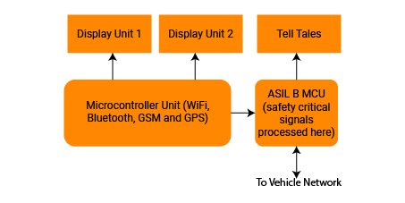
Safety analyses such as FMEA, FMEDA, FTA, etc. help in deriving failure modes, certain hardware metrics, faults, and their origin and a whole lot of relevant work products. For example, the decision to have a companion MCU to handle safety-critical signal (shown in the image below) comes from these analyses.

Digital instrument cluster, along with infotainment system, has been one of our key areas of expertise. We are also one of the early adopters of automotive functional safety as a culture in our automotive team and are proud to have delivered a large number of ISO 26262 compliant solutions to our global customers.
Get in touch with us at sales@embitel.com to learn more about our experience in this domain.


