A Hall Effect Sensor is a widely used sensor that provides rotor position feedback to a motor controller. Let’s understand the significance of this sensor in an automotive motor control system.
A BLDC motor control system is a complicated circuit where several components work in tandem to make the motor move in a desired manner. Efficiency, Durability and Performance are the attributes that concern the engineers the most while designing such a system.
While the magnets and coils take care of the electrical aspect, a microcontroller acts as the brain that drives the motor. But even the sharpest brain needs sensory inputs.
The two sensory inputs that assume much importance here are Speed and Position. Let’s understand them in the context of motor commutation.
This example will drive home the importance of a hall-effect sensor in an automotive motor controller application.
The importance of Hall effect sensors in automotive motor control solutions can be observed in electric power steering (EPS) systems. In an EPS system, a small electric motor assists the driver in turning the steering wheel, making it easier to maneuver the vehicle at low speeds.
To ensure precise control of the electric motor, Hall effect sensors are used to detect the position of the steering wheel and the motor’s rotor. These sensors provide feedback to the motor controller, which adjusts the amount of power supplied to the motor based on the driver’s input and the position of the steering wheel.
Without Hall effect sensors, the motor controller would not be able to accurately determine the position of the steering wheel or the rotor, which could lead to unstable or erratic.
Commutation is the process of switching current in the motor phases to facilitate the rotation of the motor.
In brushed motors, the brushes come in contact with the commutator and switch the current for the movement of the motors. BLDC motors do not have brushes; thus, they need to be driven electronically using a motor control system.
The BLDC motor controller provides the rectangular waveforms (voltage) to the rotor magnets, and create the magnetic field which drives the motor.
Importance of Speed and Position of the Rotor in Motor Commutation:
Commutation in a BLDC motor is a 6-step process. A 3-phase H-Bridge is used to create 6 flow vectors each causing a rotation of 60 Degrees (corresponding to the next position) of the motor, thus making a full rotation of 360 degrees.
- In order to move the motor, the motor controller sends current through the stator’s coil. This produces magnetic field which in turn develops the torque on the rotor (a permanent magnet). As a result, the rotor starts to move.
- Now, if the rotor reaches near the magnetic field that is moving it, the rotor will tend to stop because of the changed polarity. At this instance, the magnetic field will begin to attract the rotor and stop the movement. To avoid it, the motor control system switches the current supplied to the stator and a new magnetic field is created and the rotor continues its movement. The process of commutation thus, is all about switching the current at the right instance.
- The concept of speed and position comes into the picture as this ‘right instance’ needs to be sensed when it arrives.
- A sensor is required to give the feedback to the motor control system indicating when the rotor has reached the desired position. If the commutation is done faster or slower than the speed of the rotor, the magnets go out of sync with the magnetic field of the stator. This causes the rotor to vibrate and stop instead of rotating.
- Post one commutation, the position of the rotor has to be determined with respect to the stator so that the next commutation can be initiated. And hence, the position detection is also a crucial parameter.
There are many types of sensors used in the electric motor industry like Encoders, Switches and Potentiometer. However, the most widely used and deployed sensor is the Hall Effect Sensor.
In the subsequent sections, we will talk in detail about the Hall Effect Sensor and its role in a motor control system.
What is Hall Effect Sensor?
A Hall Effect Sensor is essentially a transducer based on the principle of Hall Effect.
The effect of getting a measurable voltage when a conductor or semiconductor with current flowing in one direction is introduced perpendicular to a magnetic field, is called the Hall Effect.
In simpler terms, a voltage is produced across an electric conductor when a magnetic field is applied to it in a direction perpendicular to the flow of current.
A Hall Effect Sensor is a solid-state device that applies this principle to determine the position, speed and various other attributes required to run a BLDC motor efficiently.

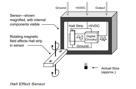
A Magnified View of the Hall Effect Sensor
A small value of current runs through the Hall Strip at all times. As already mentioned, the alternating field from this rotor magnet will create a voltage across the Hall Strip. The voltage is then fed to the digital circuitry (shown in the diagram above), which in turn, gives a digital signal as the Hall Effect Sensor output.
How Hall Effect Sensor Works in a BLDC Motor
Typically, a BLDC motor will have three Hall Effect Sensors fitted on the rotor or the stator. These Hall sensors are placed 120 degree apart from each other, giving 0 to 360 degree angle position.
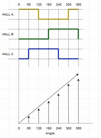
When these hall sensors come in contact with the magnetic field of the rotor, it generates respective digital pulse in terms of 1 and 0, as shown in the diagram below.
In six steps, these hall sensors are able to give the motor position (Angle). In the diagram, the rectangular waveforms showcase the positive and the negative pulse generated at the corresponding angle by all three Hall Effect Sensors – A, B and C.
A corresponding graph also shows how one commutation is completed in 6 steps as the angle reached 360 degrees.

The following explanation will bring more clarity.
When the rotor magnet crosses one of the sensors, it produces a low or high signal depending on whether it is the North pole or the South pole of the rotor that has passed. As the rotor crosses all three sensors, these sensors switch between low and high, thus giving out the position of the rotor every 60 degrees.
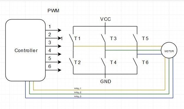
The diagram below shows a typical BLDC Motor Controller. Three lines going from the motor to the controller depict the signal sent by the three Hall Effect Sensors.

The Hall-effect Sensor is able to distinguish between the positive and negative charge moving in opposite direction. The magnetic field detected by the hall-effect sensor is converted to the suitable analog or digital signal that can be read by the electronic system, usually a motor control system.
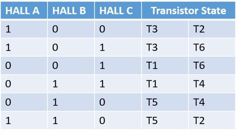
Shown below is the truth table derived from the readings of the three Hall Effect Sensors. As you can see, the transistor state of the H-Bridge depends on the signal detected by the sensor. The downward arrow shows the clockwise movement (CW) and the upward arrow shows counter clockwise movement (CCW).

Now that we have the truth table and the graph, the angle (position) and the speed of the rotor can be easily calculated.
- Angle Calculation: It is calculated based on the Hall Effect Sensor signal as shown in fig 1. According to the Hall sensor pulse, 0 – 360 degree angle is calculated.
- Speed Calculation: Speed calculation is done by calculating periods of the Hall Effect Sensor signal. With the help of period, frequency and speed are calculated as per the following formula.Frequency = 1 / Period.
Only one hall sensor is enough for calculating the speed.
Advantages of Using a Hall Effect Sensor in a BLDC Motor Controller
- Hall Effect Sensor is a very simple device comprising of magnets, hence, very cost-effective for motor control systems.
- For the same reason, these sensors are easy to implement in advanced motor control systems for EVs and other automotive solutions.
- Most BLDC motors come equipped with these sensors.
- Hall Effect Sensors are mostly immune to environmental conditions like humidity, temperature, dust and vibration.
How does Hall-effect Sensors Improve EV Performance
While internal combustion engines have auxiliary systems running on electric motors such as ABS and power windows, electric vehicle’s drivetrain itself runs on motors. In such case, hall-effect sensors become all the more important as their accuracy directly impacts the EV’s performance.
The use of Hall effect sensors in electric vehicles allows for precise monitoring and control of the motor’s speed and position, which in turn enables the vehicle to deliver efficient and reliable performance. For example, the sensor allows the vehicle to accurately control the motor’s torque output, which is essential for maintaining the vehicle’s stability and traction control.
The Hall effect sensor also has some role to play in regenerative braking, which is a key feature of electric vehicles. It allows them to recover energy during braking and store it in the battery for later use. This not only improves the vehicle’s overall energy efficiency, but also extends the vehicle’s range which is USP of any EV model.
In addition, the Hall effect sensor also plays a role in the safety of electric vehicles. By monitoring the position of the wheels and other components, the sensor can detect any potential issues or malfunctions in the system. The diver can be alerted in time and corrective action can be taken to prevent accidents or damage to the vehicle.
Wrapping it up
A lot goes on inside a BLDC motor control system. There’s FOC algorithm, H-Bridge circuits, efficient commutation and more. Amongst the multitude of components inside a BLDC motor control system, a very small and humble sensor – the Hall Effect Sensor, makes its presence felt.
Being cost-effective and easy to implement, these sensors have made new-age BLDC motor control solutions more efficient and deployment-friendly in the automotive industry.
Watch this space to know about other such components that play vital roles inside a BLDC motor controller.


